
Testing that requires the use of strain gages often consume large amounts of resources and effort to prepare for. One way to reduce the amount of time and energy spent configuring a test is to use sensors that support the Transducer Electronic Data Sheet (TEDS) interface. Many VTI measurement instruments support TEDS sensors including the EX1629 48-channel high-performance strain gage measurement instrument, EX1403 16-channel bridge/strain gage instrument, and the RX1024 24-channel bridge/strain gage instrument.
Depending on the number of channels in your test system, using TEDS sensors can significantly reduce test setup time. You simply plug transducer cables into the instrument making the measurements. The software in your instrument takes care of the rest – it downloads the electronic data sheet from the sensor and properly configures the channel.
As specified in IEEE 1451.4-2004, IEEE Standard for A Smart Transducer Interface for Sensors and Actuators--Mixed-Mode Communication Protocols and Transducer Electronic Data Sheet (TEDS) Formats, a TEDS contains the information needed by an instrument or measurement system to identify, characterize, interface, and use the signal from an analog sensor. The way that the standard defines a TEDS allows the use of very small memories, and this, in turn, allows TEDS to be included in small, lightweight sensors.
The Basic TEDS consists of 64 bits which contains the:
- Manufacturer ID
- Model Number
- Version Letter
- Version Number
- Serial Number
Other data about the transducer is stored in templates that follow the Basic TEDS. The sensor's calibration data, for example, would be contained in one of these templates. The standard defines templates for common types of transducers. These are shown in Table 1 below.
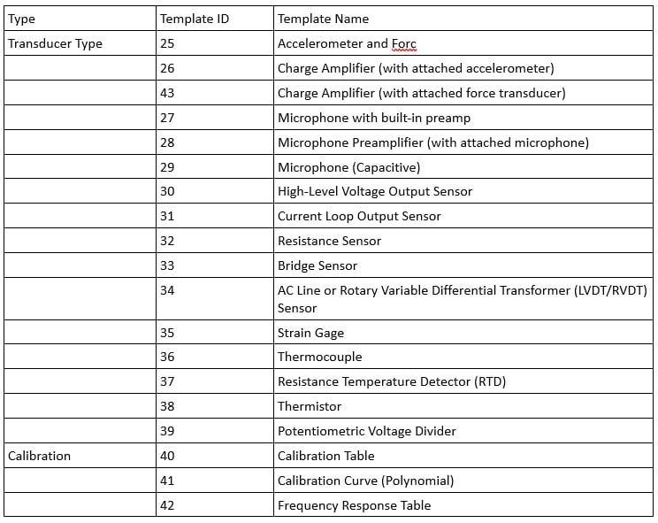
Table 1. IEEE 1541.4 standard templates
IEEE 1451.4 also defines the physical connection between a transducer and an instrument. The Mixed-Mode Interface (MMI) is used for both TEDS data and analog signals, on either 2, 3 or 4 wires. This allows a wide variety of sensors and actuators to include a TEDS.
VTI EX1629 TEDS support
The EX1629 supports reading and writing to TEDS devices that implement the IEEE 1451.4 standard. Each channel (0 through 47) functions as a 1-Wire bus master, although only one channel can be active at a time, reading, or writing. Only one TEDS device per channel is supported.
There are two software interfaces to support TEDS devices. One that is designed specifically to use the Dallas/Maxim DS2430 IC. The second is more general purpose and will work with any 1-Wire TEDS device, implementing the MicroLAN (MLAN) protocol. The MLAN interface, documented in IEEE 1451.4-2004 Annex G, is a more general-purpose interface and all new applications should use this interface.
For more information on TEDS and how to use TEDS sensors in your test system, contact one of our sales representative by visiting powerandtest.com/sales. You can also email us at sales.ppd@ametek.com or call 800-733-5427 or 858-450-0085.