
In order to perform an accurate test of solar array inverters, the output of a solar array simulator must faithfully follow the I-V curve of a solar array or solar panel. That is to say that it must respond just as a solar array would to the changing load conditions imposed by the inverter under test. In order to evaluate how well a simulator can do this, you need to consider three parameters: output noise current, phase error between output voltage and current, and the maximum power point (MPP) tracking accuracy.
Excessive output noise current will make it difficult, if not impossible for an inverter to find the maximum power point. We have found that any noise level above 100 mA, can cause test problems. The Elgar TerraSAS has an output noise current of less than 70 mA.
In the real world, there is essentially zero phase difference between the output voltage and output current of a solar panel or array, even when inverters use MPP tracking strategies that change the load very quickly. To accurately simulate a solar panel or array, therefore, it is important that the phase error of the simulator be less than 15 degrees even if the load is changing that quickly. Many simulators are unable to do this, making them unsuitable for testing those inverters that use high sweep frequencies.
In an extreme case, when the phase error between the output voltage and output current approaches +/- 90 deg, the inverter under test will actually begin seeking the MPP in the wrong direction and will become unstable. With a significant phase error, even if the inverter is stable it will lock onto a curve location that is not the MPP. The amount of error is proportional to the phase error. We have observed this behavior on microinverters and residential inverters that use fast MPP tracking algorithms.
Another important specification is the maximum power point dynamic tracking accuracy. This is a measure of how much a simulator will deviate from a programmed I-V curve under dynamic conditions. Many factors contribute to this inaccuracy.
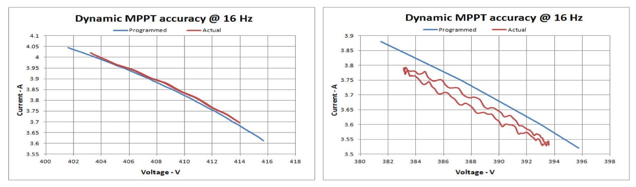 The figure above shows a comparison of the dynamic MPP tracking accuracy of two simulators currently on the market. A test frequency of 16 Hz was used for this test to simulate the loading effect of an inverter. The blue line shows the ideal response of the simulator, while the red lines show the actual response. As you can see, there is quite a difference between the two simulators, and the difference is even higher as the dithering frequency increases. The simulator whose output is shown on the left—an Elgar TerraSAS Solar Array Simulator—will perform a much more accurate test than the one whose output is shown on the right.
The TerraSAS consists of programmable DC power supplies, a rack mounted controller, keyboard and LCD display with control software and GUI interface, output isolation and polarity reversing relays and a unique PV simulation engine that controls the power supply. This combination of hardware allows the TerraSAS to simulate most test protocols or combination of events that a solar installation will be subjected to. Power supplies are available in 1-15 kW increments to simulate arrays up to 1 MW.