
Electronic loads are used in a variety of tests, including power supply tests and battery tests. You can program them to provide exactly the kind of load that you need for the device you are testing.
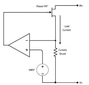
One of the most common ways to use an electronic load is in the constant current (CC) mode. In this mode, the electronic load will draw a constant current from the device under test (DUT), no matter what the output voltage is. The figure below shows a simplified schematic of an electronic load to illustrate how the CC mode works.
Current from the device under test flows through both the power FET and the current shunt resistor. The voltage across the shunt resistor is compared to a voltage reference and the difference between the two is used to control the drain-to-source resistance, RDS, of the power FET. If the load current is higher than the desired constant current, the circuit will adjust the FET's gate voltage to increase RDS and thus reduce the load current. If the load current is lower than the desired constant current, the circuit will adjust the gate voltage to reduce RDS, and the load current will increase.
In an actual electronic load, VREF is supplied by a digital-to-analog converter (DAC). The user sets the DAC output voltage to yield the desired constant-curent level. The CC accuracy specification is largely determined by the accuracy of the digital-to-analog converter used in this circuit.
Constant-voltage mode
Most electronic loads also offer a constant-voltage (CV) mode. In this mode, the electronic load will maintain a constant voltage across the device under test. You would use this mode to test a battery charging circuit. The figure below shows a simplified schematic for an electronic load operating in constant-voltage mode.
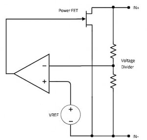
In CV mode, the feedback signal is generated by a precision voltage divider. This signal is again compared to a voltage reference, and the output of the comparator is used to increase or decrease the RDS of the power FET. This basically changes the input impedance of the electronic load, allowing it to maintain a constant voltage across the input terminals, no matter how much current it is sinking.
Just like the CC mode, VREF is normally supplied by a digital-to-analog converter. Changing its output will change the CV value.
Modern electronic loads also offer constant-resistance (CR) and constant-power (CP) modes. The circuits used to implement these modes are usually some variation of the circuits used for the CC and CV modes. For more information on how electronic loads work, and how to use them in your application, contact AMETEK Programmable Power. You can send an e-mail to sales.ppd@ametek.com or phone 800-733-5427.