
When installing an AMETEK Programmable Power power source, you must properly size the wires you use to connect the AC input power to the power source and the AC or DC output to the load. Selecting the right size gauge wire will ensure that your power source will operate efficiently and reliably.
The tables below will help you determine the appropriate wire size for both the input and output connections. Table 1 gives minimum recommended gauge wire size for copper wire operating at a maximum of 30° C ambient temperature. The data in this table comes from the National Electrical Code, and is for reference only. Local codes can impose different requirements, so make sure to check them before making a final installation. To handle higher currents, wires can be paralleled; refer to the National Electrical Code for guidelines.
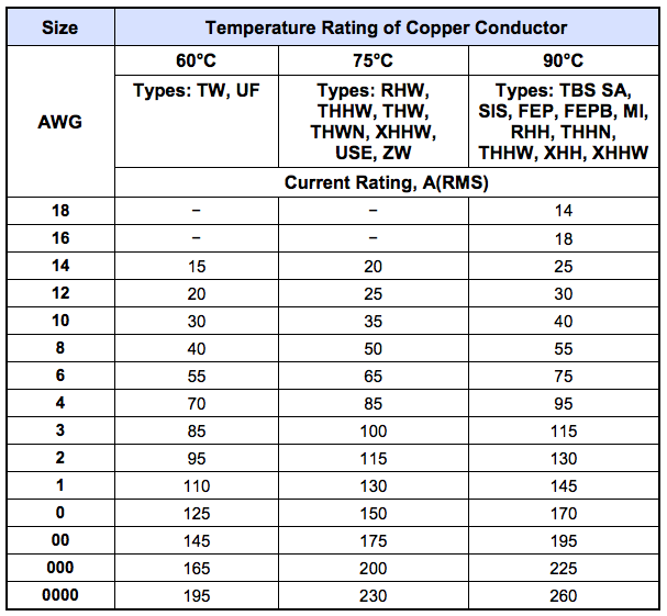 Table 1.
There are two main reasons for choosing the right size wire for the load. The first reason is to ensure that the cable can safely carry the maximum load current without overheating, which may present a fire hazard or cause the insulation to degrade. The second reason is to minimize the IR voltage drop across the cable. Both of these phenomena have a direct effect on the quality of power delivered to and from the power source and corresponding loads.
If the ambient temperature of the installation is greater than 30° C, consider using a larger gauge wire than shown in Table 1. The ability of a wire to carry current, also called its ampacity, decreases as the ambient temperature increases. So, use short cables with a larger gauge wire than shown in Table 1. And, if power cables are to be bundled with other cables, you may have to derate even further, as the operating temperature inside the bundle may be higher than the ambient temperature.
Also, be careful when using published commercial utility wiring codes. These codes are designed for the internal wiring of homes and buildings, and while they do take into account safety factors, such as wiring loss, heat, breakdown insulation, and aging, they allow a voltage drop of 5%. Such a high voltage drop may not be acceptable in your application.
In high performance applications where loads draw high inrush or transient currents, make sure to consider the peak currents that the cables may have to accommodate. These peak currents may be up to five times the RMS current values. An underrated wire gauge adds losses, which alter the inrush characteristics of the application and thus the expected performance.
Table 2 shows the ampacity, resistance per 100 ft, and voltage drop per 100 ft. at the rated current, at an ambient temperature of 20° C. Copper wire has a temperature coefficient of α = 0.00393Ω/°C at t1 = 20°C, so that at an elevated temperature, t2, the resistance would be R2 = R1 (1 + α (t2 - t1)).
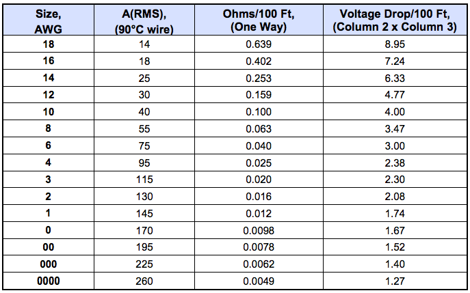 Table 2.
The output power cables must be large enough to prevent the line voltage drop (the sum of the voltage drops across both output wires) between the power source and the load from exceeding the remote sense capability of the power source. Calculate the voltage drop using the following formula: Voltage Drop = 2 × distance-in-feet × cable-resistance-per-foot × current.
For more information on right gauge wire for your application, contact AMETEK Programmable Power. You can send an e-mail to sales.ppd@ametek.com or phone 800-733-5427.