
Today, when we think about controlling the output of a power supply, we usually think about digital control via a USB port or some other network interface. That's not the only way to control a power supply, though. Analog control is still used in many industrial applications, and it’s also a good choice if you have fairly simple control needs.
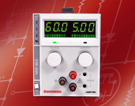
The optional Analog Programming (APG) Interface allows you to control the Sorensen XT and HPD Series DC power supplies with either 0-10 VDC signal or a 0-10 kΩ resistance. You connect these signals to the power supply via a female DB-25 connector on the unit's rear panel.
The APG's interface provides the following features:
- Programmable output voltage and programmable current limit using either a 0-10 VDC programming signal or a 0-10 kΩ resistance. In this mode, both the offset and range are externally adjustable.
- Fixed programming of output voltage and/or current limit using an available 10V reference (10mA max source).
- 0-10 V readback of output voltage and current with externally adjustable offset and range.
- Status signals for programming mode, operating mode, OVP (over voltage protection) flag, and output fail flag.
- Adjustable over-voltage protection (OVP) with reset and flag.
- TTL shutdown with selectable positive or negative logic.
- Tracking for multiple supplies of the same output.
The performance specifications are shown in Table 1 below:
| Remote Analog Programming |
0-10 VDC for 0-100% of rated voltage or current ±0.1%, 0-10 kΩ for 0-100% of rated voltage or current ±0.1% |
| OVP Trip Range | 3V to full output + 10% |
| Remote ON/OFF | 2 to 25Vdc high. <0.8Vdc low. User-selectable logic |
| Tracking Accuracy | ±1% |
As an example of how to use the features of the APG interface, let's look at how to program the supply's output voltage with a 0-10 VDC voltage source:
- Select remote voltage programming by moving the rear panel switch S1-5 (remote voltage program select) to the ON (closed) position. Or, connect J5 pin 7 (remote voltage program select) to J5 pin 6 (auxiliary ground). As these two control functions are wired in parallel, they function as a logic OR.
- Connect the voltage source between pin 17 (voltage program) and either pin 4 or pin 5 (program return).
- Vary the external voltage from 0-10 VDC to cause the power supply output to vary from 0-100% of rated output voltage. You may set the power supply's output current limit using another source or the front panel current limit control.
The procedure for programming the output voltage with a 0-10 kΩ resistance and programming the output current with either a 0-10 VDC signal or a 0-10 kΩ resistance is very similar to this.
For more information on how to use remote analog programming, or isolating control signals, contact AMETEK Programmable Power via e-mail sales.ppd@ametek.com or call 800-733-5427.