While these days, computer control is usually the preferred method of controlling a power supply, many AMETEK Programmable Power products, such as the Sorensen SGA Series still offer analog control. Analog control is still used in many industrial applications, and it's also a good choice if you have fairly simple control needs.
The SGA Series allows you to control the output with an analog signal in eight different ways:
- Turn the power supply on and off with an analog signal, switch closure, or TTL/CMOS signal.
- Set the output voltage with a 0 – 5 VDC signal.
- Set the output voltage with a 0 – 10 VDC signal.
- Set the output voltage by resistance (0 – 5 kΩ).
- Set the output current with a 0 – 5 VDC signal.
- Set the output current with a 0 – 10 VDC signal.
- Set the output current by resistance (0 – 5 kΩ).
- Set the over-voltage protection (OVP) trip level with a 0.25 – 5.5 VDC signal.
You connect the control signals to an SG Series power supply via J1. It is labelled “ANALOG CONTROL.”
Setting the output voltage with a 0 – 5 V signal
As an example, let's look at how to use a 0 – 5 VDC signal to control the output voltage. As shown in Figure 1 below, you connect the DC voltage source between J1, pin 9 (VP 5 V) and J1, pin 20 (VP RTN). Note that VP RTN must be within ±3 V, of the circuit common (J1, pin 6, COM). In this example, we connect pin 20 directly to pin 6 (COM), so it's at the same potential. J1, pin 5 is the ON/OFF input and must be connected to COM to enable the power supply output.
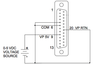
When connected this way, the output voltage, Vout = (Vdc/ 5 VDC) * 100% rated output voltage, with Vdc in volts.
Details on how to connect and use the other analog control signals can be found in the Sorensen SGA Series DC Power Supply Operation Manual.
Isolating control signals
In some applications, you may need to isolate these control signals from the power supply. To do this, you need the Remote Isolated Analog Interface Control Option.
This option uses the same Analog Control connector (J1) as the standard interface, but fully isolates the remote control signals and allows control of units not connected to a common ground. Control signal returns are isolated from output power negative terminal. Isolating these signals protects the power supply from potential damage from systems with high energy electrical potentials or large ground loop currents.
For more information on how to use remote analog programming, or isolating control signals, contact AMETEK Programmable Power by sending an e-mail to sales.ppd@ametek.com or phoning 800-733-5427.